Product Description
Product DescriptionHydraulic Cylinders, Jacks, Lifting Products and SystemsEnerpac provides the largest selection of cylinders and lifting systems, fully supported and available through the most extensive network of distributors worldwide. We have a solution for virtually any application – lifting, pushing, pulling, bending or holding – in most industrial and commercial work environments. CHINAMFG offers hundreds of different configurations of mechanical and hydraulic cylinders and lifting systems, plus products ranging from hydraulic jacks for portability and tight fits, to engineered systems for precise control over multiple lift points. General Purpose Hydraulic CylindersEnerpac general purpose cylinders are available in hundreds of different mechanical or hydraulic cylinder configurations. Whatever the industrial application; lifting, pushing, pulling and available in range of force capacities, stroke lengths or size restrictions. Single acting, hollow plunger, or low height, you can be sure that CHINAMFG has the hydraulic jack to suit your high force application. RC, RSM, RCS, CLP, RCH, RRH, BRC, BRP, SC-series
1>. RR-Series, Double-Acting CylindersEnerpac double acting cylinders are rugged enough for the toughest job site uses, and precision designed for high cycle industrial use.Collar threads, plunger threads and base mounting holes for easy fixturing (on most models)Baked enamel finish for increased corrosion resistanceRemovable hardened saddles protect plunger during lifting and pressingBuilt-in safety valve prevents accidental over-pressurizationCR-400 couplers included on all cylinder modelsPlunger wiper reduces contamination, extending cylinder life
| Cyl. Capacity |
Stroke | Model Number |
Max. Cylinder Capacity |
Effective Area |
Oil Capa- city |
Coll. Height |
Ext. Height |
Out- side Dia. |
Wt. | |||
| kN | cm2 | cm3 | ||||||||||
| ton (kN) | mm | Push | Pull | Push | Pull | Push | Pull | mm | mm | mm | kg | |
| 10 (101) |
254 | RR-1571* | 101 | 33 | 14,5 | 4,8 | 368 | 122 | 409 | 663 | 73 | 12 |
| 305 | RR-1012* | 101 | 33 | 14,5 | 4,8 | 442 | 147 | 457 | 762 | 73 | 14 | |
| 30 (295) |
209 | RR-308* | 295 | 53 | 42,1 | 19,1 | 879 | 400 | 395 | 604 | 101 | 18 |
| 368 | RR-3014* | 295 | 53 | 42,1 | 19,1 | 1549 | 703 | 549 | 917 | 101 | 29 | |
| 50 (498) |
156 | RR-506 | 498 | 103 | 71,2 | 21,5 | 1111 | 335 | 331 | 487 | 127 | 30 |
| 334 | RR-5013 | 498 | 103 | 71,2 | 21,5 | 2378 | 718 | 509 | 843 | 127 | 52 | |
| 511 | RR-5571 | 498 | 103 | 71,2 | 21,5 | 3638 | 1099 | 733 | 1244 | 127 | 68 | |
| 75 (718) |
156 | RR-756 | 718 | 156 | 102,6 | 31,4 | 1601 | 490 | 347 | 503 | 146 | 41 |
| 333 | RR-7513 | 718 | 156 | 102,6 | 31,4 | 3417 | 1046 | 525 | 858 | 146 | 68 | |
| 95 (933) |
168 | RR-1006 | 933 | 435 | 133,3 | 62,2 | 2238 | 1045 | 357 | 525 | 177 | 61 |
| 333 | RR-10013 | 933 | 435 | 133,3 | 62,2 | 4439 | 2071 | 524 | 857 | 177 | 93 | |
| 460 | RR-10018 | 933 | 435 | 133,3 | 62,2 | 6132 | 2861 | 687 | 1147 | 177 | 117 | |
| 140 (1386) |
57 | RR-1502 | 1386 | 668 | 198,1 | 95,4 | 1129 | 544 | 196 | 253 | 203 | 49 |
| 156 | RR-1506 | 1386 | 668 | 198,1 | 95,4 | 3090 | 1488 | 385 | 541 | 203 | 93 | |
| 333 | RR-15013 | 1386 | 668 | 198,1 | 95,4 | 6597 | 3177 | 582 | 915 | 203 | 124 | |
| 815 | RR-15032 | 1386 | 668 | 198,1 | 95,4 | 16145 | 7775 | 1116 | 1931 | 203 | 238 | |
| 200 (1995) |
152 | RR-2006 | 1995 | 1017 | 285,0 | 145,3 | 4332 | 2209 | 430 | 582 | 247 | 147 |
| 330 | RR-20013 | 1995 | 1017 | 285,0 | 145,3 | 9405 | 4795 | 608 | 938 | 247 | 199 | |
| 457 | RR-20018 | 1995 | 1017 | 285,0 | 145,3 | 13571 | 6640 | 765 | 1222 | 247 | 204 | |
| 610 | RR-20571 | 1995 | 1017 | 285,0 | 145,3 | 17385 | 8863 | 917 | 1527 | 247 | 279 | |
| 914 | RR-20036 | 1995 | 1017 | 285,0 | 145,3 | 26049 | 13280 | 1222 | 2136 | 247 | 383 | |
| 1219 | RR-20048 | 1995 | 1017 | 285,0 | 145,3 | 34741 | 17712 | 1527 | 2746 | 247 | 483 | |
| 325 (3201) |
153 | RR-3006 | 3201 | 1703 | 457,3 | 243,2 | 6997 | 3721 | 485 | 638 | 311 | 200 |
| 305 | RR-30012 | 3201 | 1703 | 457,3 | 243,2 | 13947 | 7418 | 638 | 943 | 311 | 312 | |
| 457 | RR-30018 | 3201 | 1703 | 457,3 | 243,2 | 20889 | 11114 | 790 | 1247 | 311 | 385 | |
| 609 | RR-30571 | 3201 | 1703 | 457,3 | 243,2 | 27850 | 14811 | 943 | 1552 | 311 | 469 | |
| 915 | RR-30036 | 3201 | 1703 | 457,3 | 243,2 | 41843 | 22253 | 1247 | 2162 | 311 | 628 | |
| 1219 | RR-30048 | 3201 | 1703 | 457,3 | 243,2 | 55745 | 29646 | 1552 | 2771 | 311 | 780 | |
| 440 (4292) |
152 | RR-4006 | 4292 | 2297 | 613,1 | 328,1 | 9319 | 4987 | 528 | 690 | 358 | 303 |
| 305 | RR-40012 | 4292 | 2297 | 613,1 | 328,1 | 18700 | 10007 | 690 | 995 | 358 | 399 | |
| 457 | RR-40018 | 4292 | 2297 | 613,1 | 328,1 | 28018 | 14995 | 843 | 1300 | 358 | 453 | |
| 610 | RR-40571 | 4292 | 2292 | 613,1 | 328,1 | 37400 | 20014 | 995 | 1605 | 358 | 597 | |
| 914 | RR-40036 | 4292 | 2292 | 613,1 | 328,1 | 56037 | 29988 | 1300 | 2214 | 358 | 792 | |
| 1219 | RR-40048 | 4292 | 2292 | 613,1 | 328,1 | 74737 | 39996 | 1605 | 2824 | 358 | 980 | |
| 520 (5108) |
153 | RR-5006 | 5108 | 2838 | 729,7 | 405,4 | 11164 | 6203 | 577 | 730 | 397 | 432 |
| 305 | RR-50012 | 5108 | 2838 | 729,7 | 405,4 | 22256 | 12365 | 730 | 1035 | 397 | 589 | |
| 457 | RR-50018 | 5108 | 2838 | 729,7 | 405,4 | 33347 | 18526 | 882 | 1339 | 397 | 680 | |
| 609 | RR-50571 | 5108 | 2838 | 729,7 | 405,4 | 44440 | 24689 | 1032 | 1644 | 397 | 816 | |
| 925 | RR-50036 | 5108 | 2838 | 729,7 | 405,4 | 66768 | 36973 | 1339 | 2254 | 397 | 1002 | |
| 1219 | RR-50048 | 5108 | 2838 | 729,7 | 405,4 | 88951 | 49418 | 1644 | 2863 | 397 | 1224 | |
2>. CLP-Series, Pancake Lock Nut CylindersEnerpac pancake lock nut cylinders have an extremely low height for use in confined areasLock nut for positive and safe mechanical load holding over a long period of timeSingle-acting, load returnOptional special synthetic coating for improved corrosion resistance and lower friction for smoother operationOverflow port functions as a stroke limiterCR-400 coupler and dust cap included on all models.
| Cylinder Capacity |
Stroke | Model Number |
Cylinder Effective Area |
Oil Capacity |
Collapsed Height |
Extended Height |
Outside Diameter |
Weight |
| ton (kN) | mm | cm2 | cm3 | mm | mm | mm | kg | |
| 60 (606) | 50 | CLP-602 | 86,6 | 432 | 125 | 175 | 140 | 15 |
| 100 (1571) | 50 | CLP-1002 | 146,8 | 734 | 137 | 187 | 175 | 26 |
| 160 (1619) | 45 | CLP-1602 | 231,3 | 1040 | 148 | 193 | 220 | 44 |
| 200 (1999) | 45 | CLP-2002 | 285,6 | 1285 | 155 | 200 | 245 | 57 |
| 260 (2567) | 45 | CLP-2502 | 366,8 | 1650 | 159 | 204 | 275 | 74 |
| 400 (3916) | 45 | CLP-4002 | 559,5 | 2517 | 178 | 223 | 350 | 134 |
| 520 (5114) | 45 | CLP-5002 | 730,6 | 3287 | 192 | 237 | 400 | 189 |
3>. RSM, RCS-Series, Low Height Hydraulic CylindersRSM-Series, Flat-JacCylindersCompact hydraulic cylinder wtih a flat design for use where most other cylinders will not fitSingle-acting, spring returnRSM-750, 1000 and 1500 cylinders have handles for easy carryingMounting holes permit easy fixturing Baked enamel finish for increased corrosion resistanceCR-400 coupler and dust cap included on all models1)Hard chrome plated high quality steel plungersGrooved plunger ends require no saddle.RCS-Series, Low Height CylindersLightweight, low profile cylinder design for use in confined spacesSingle-acting, spring returnBaked enamel finish for increased corrosion resistancePlunger wiper reduces contamination, extending cylinder lifeCR-400 coupler and dust cap included on all modelsGrooved plunger end with threaded holes for mounting tilt saddlesIntegral handle on RCS-1002 for easy carryingPlated steel plungers.
| Cylinder Capacity |
Stroke | Model Number |
Cylinder Effective Area |
Oil Capacity |
Collapsed Height |
Extended Height |
Outside Diameter |
Weight |
| ton (kN) | mm | cm2 | cm3 | mm | mm | mm | kg | |
| 5 (45) | 6 | RSM-501) | 6,5 | 4 | 32 | 38 | 58 x 41 | 1 |
| 10 (101) | 12 | RSM-100 | 14,5 | 18 | 43 | 54 | 82 x 55 | 1,4 |
| 20 (201) | 11 | RSM-200 | 28,7 | 32 | 51 | 62 | 101 x 76 | 3,1 |
| 30 (295) | 13 | RSM-300 | 42,1 | 55 | 58 | 71 | 117 x 95 | 4,5 |
| 45 (435) | 16 | RSM-500 | 62,1 | 99 | 66 | 82 | 140 x 114 | 6,8 |
| 75 (718) | 16 | RSM-750 | 102,6 | 164 | 79 | 95 | 165 x 139 | 11,3 |
| 90 (887) | 16 | RSM-1000 | 126,7 | 203 | 85 | 101 | 178 x 153 | 14,5 |
| 150 (1368) | 16 | RSM-1500 | 198,1 | 317 | 100 | 116 | 215 x 190 | 26,3 |
| 10 (101) | 38 | RCS-101* | 14,5 | 55 | 88 | 126 | 69 | 2,7 |
| 20 (201) | 45 | RCS-201* | 28,7 | 129 | 98 | 143 | 92 | 5,0 |
| 30 (295) | 62 | RCS-302* | 42,1 | 261 | 117 | 179 | 101 | 6,8 |
| 45 (435) | 60 | RCS-502* | 62,1 | 373 | 122 | 182 | 124 | 10,0 |
| 90 (887) | 57 | RCS-1002* | 126,7 | 722 | 141 | 198 | 165 | 20,7 |
| Material: | Steel |
|---|---|
| Usage: | Lifting Equipment |
| Structure: | General Cylinder |
| Power: | Hydraulic |
| Standard: | Standard |
| Pressure Direction: | Single-acting Cylinder |
| Customization: |
Available
|
|
|---|
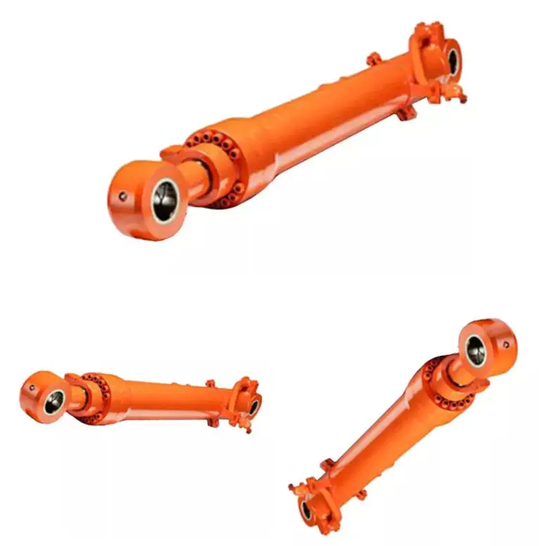
How do hydraulic cylinders handle the challenges of minimizing friction and wear?
Hydraulic cylinders employ several mechanisms and techniques to effectively minimize friction and wear, ensuring optimal performance and longevity. Minimizing friction and wear is crucial for hydraulic cylinders as it helps to maintain efficiency, reduce energy consumption, and prevent premature failure. Here’s a detailed explanation of how hydraulic cylinders handle the challenges of minimizing friction and wear:
1. Lubrication:
– Proper lubrication is essential for minimizing friction and wear in hydraulic cylinders. Lubricating fluids, such as hydraulic oils, are used to create a thin film between moving surfaces, reducing direct metal-to-metal contact. This lubricating film acts as a protective barrier, reducing friction and preventing wear. Regular maintenance practices include monitoring and maintaining the appropriate lubricant levels to ensure optimal lubrication and minimize frictional losses.
2. Surface Finishes:
– The surface finishes of components in hydraulic cylinders play a crucial role in minimizing friction and wear. Smoother surface finishes, achieved through precision machining, grinding, or the application of specialized coatings, reduce surface roughness and frictional resistance. By minimizing surface irregularities, the risk of wear and friction-induced damage is significantly reduced, resulting in improved efficiency and extended component life.
3. High-Quality Sealing Systems:
– Well-designed and high-quality sealing systems are crucial for minimizing friction and wear in hydraulic cylinders. Seals prevent fluid leakage and contamination while maintaining proper lubrication. Advanced sealing materials, such as polyurethane or composite materials, offer excellent wear resistance and low friction characteristics. Optimal seal design and proper installation ensure effective sealing, minimizing friction and wear between the piston and cylinder bore.
4. Proper Alignment and Clearances:
– Hydraulic cylinders must be properly aligned and have appropriate clearances to minimize friction and wear. Misalignment or excessive clearances can result in increased friction and uneven wear, leading to premature failure. Proper installation, alignment, and maintenance practices, including regular inspection and adjustment of clearances, help ensure smooth and even movement of the piston within the cylinder, reducing friction and wear.
5. Filtration and Contamination Control:
– Effective filtration and contamination control are essential for minimizing friction and wear in hydraulic cylinders. Contaminants, such as particles or moisture, can act as abrasive agents, accelerating wear and increasing friction. By implementing robust filtration systems and proper maintenance practices, hydraulic systems can prevent the ingress of contaminants, ensuring clean and properly lubricated components. Clean hydraulic fluids help minimize wear and friction, contributing to improved performance and longevity.
6. Material Selection:
– The selection of appropriate materials for hydraulic cylinder components is crucial in minimizing friction and wear. Components subject to high frictional forces, such as pistons and cylinder bores, can be made from materials with excellent wear resistance, such as hardened steel or composite materials. Additionally, selecting materials with low coefficients of friction helps reduce frictional losses. Proper material selection ensures durability and minimized wear in critical components of hydraulic cylinders.
7. Maintenance and Regular Inspection:
– Regular maintenance and inspection practices are vital for identifying and addressing potential issues that could lead to increased friction and wear in hydraulic cylinders. Scheduled maintenance includes lubrication checks, seal inspections, and monitoring of clearances. By promptly detecting and rectifying any signs of wear or misalignment, hydraulic cylinders can be kept in optimal condition, minimizing friction and wear throughout their operational lifespan.
In summary, hydraulic cylinders employ various strategies to handle the challenges of minimizing friction and wear. These include proper lubrication, employing suitable surface finishes, utilizing high-quality sealing systems, ensuring proper alignment and clearances, implementing effective filtration and contamination control measures, selecting appropriate materials, and conducting regular maintenance and inspections. By implementing these practices, hydraulic cylinders can minimize friction and wear, ensuring smooth and efficient operation while extending the overall lifespan of the system.
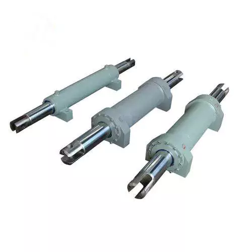
Ensuring Stable Performance of Hydraulic Cylinders Under Fluctuating Loads
Hydraulic cylinders are designed to provide stable performance even under fluctuating loads. They achieve this through various mechanisms and features that allow for efficient load control and compensation. Let’s explore how hydraulic cylinders ensure stable performance under fluctuating loads:
- Piston Design: The piston inside the hydraulic cylinder plays a crucial role in load control. It is typically equipped with seals and rings that prevent leakage of hydraulic fluid and ensure effective transfer of force. The piston design may incorporate features such as stepped or tandem pistons, which provide enhanced load-bearing capabilities and improved stability by distributing the load across multiple surfaces.
- Cylinder Cushioning: Hydraulic cylinders often incorporate cushioning mechanisms to minimize the impact and shock caused by fluctuating loads. Cushioning can be achieved through various methods, such as adjustable cushion screws, hydraulic cushioning valves, or elastomeric cushioning rings. These mechanisms slow down the piston’s movement near the end of the stroke, reducing the impact and preventing sudden stops that could lead to instability.
- Pressure Compensation: Fluctuating loads can result in pressure variations within the hydraulic system. To ensure stable performance, hydraulic cylinders are equipped with pressure compensation mechanisms. These mechanisms maintain a consistent pressure level in the system, regardless of load changes. Pressure compensation can be achieved through the use of pressure relief valves, compensating pistons, or pressure-compensated flow control valves.
- Flow Control: Hydraulic cylinders often incorporate flow control valves to regulate the speed of the cylinder’s movement. By controlling the flow rate of hydraulic fluid, the cylinder’s motion can be adjusted to match the changing load conditions. Flow control valves allow for smooth and controlled movement, preventing abrupt changes that could lead to instability.
- Feedback Systems: To ensure stable performance under fluctuating loads, hydraulic cylinders can be integrated with feedback systems. These systems provide real-time information on the cylinder’s position, velocity, and force. By continuously monitoring these parameters, the hydraulic system can make immediate adjustments to maintain stability and compensate for load fluctuations. Feedback systems can include position sensors, pressure sensors, or load sensors, depending on the specific application.
- Proper Sizing and Selection: Ensuring stable performance under fluctuating loads starts with proper sizing and selection of hydraulic cylinders. It is crucial to choose cylinders with appropriate bore size, rod diameter, and stroke length to match the anticipated load conditions. Oversized or undersized cylinders can lead to instability and reduced performance. Proper sizing also involves considering factors such as the required force, speed, and duty cycle of the application.
In summary, hydraulic cylinders ensure stable performance under fluctuating loads through features such as piston design, cushioning mechanisms, pressure compensation, flow control, feedback systems, and proper sizing and selection. These mechanisms and considerations allow hydraulic cylinders to provide consistent and controlled movement, even in dynamic load conditions, resulting in reliable and stable performance.
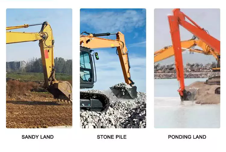
How do hydraulic cylinders generate force and motion using hydraulic fluid?
Hydraulic cylinders generate force and motion by utilizing the principles of fluid mechanics, specifically Pascal’s law, in conjunction with the properties of hydraulic fluid. The process involves the conversion of hydraulic energy into mechanical force and linear motion. Here’s a detailed explanation of how hydraulic cylinders achieve this:
1. Pascal’s Law:
– Hydraulic cylinders operate based on Pascal’s law, which states that when pressure is applied to a fluid in a confined space, it is transmitted equally in all directions. In the context of hydraulic cylinders, this means that when hydraulic fluid is pressurized, the force is evenly distributed throughout the fluid and transmitted to all surfaces in contact with the fluid.
2. Hydraulic Fluid and Pressure:
– Hydraulic systems use a specialized fluid, typically hydraulic oil, as the working medium. This fluid is stored in a reservoir and circulated through the system by a hydraulic pump. The pump pressurizes the fluid, creating hydraulic pressure that can be controlled and directed to various components, including hydraulic cylinders.
3. Cylinder Design and Components:
– Hydraulic cylinders consist of several key components, including a cylindrical barrel, a piston, a piston rod, and various seals. The barrel is a hollow tube that houses the piston and allows for fluid flow. The piston divides the cylinder into two chambers: the rod side and the cap side. The piston rod extends from the piston and provides a connection point for external loads. Seals are used to prevent fluid leakage and maintain hydraulic pressure within the cylinder.
4. Fluid Input and Motion:
– To generate force and motion, hydraulic fluid is directed into one side of the cylinder, creating pressure on the corresponding surface of the piston. This pressure is transmitted through the fluid to the other side of the piston.
5. Force Generation:
– The force generated by a hydraulic cylinder is a result of the pressure applied to a specific surface area of the piston. The force exerted by the hydraulic cylinder can be calculated using the formula: Force = Pressure × Area. The area is determined by the diameter of the piston or the piston rod, depending on which side of the cylinder the fluid is acting upon.
6. Linear Motion:
– As the pressurized hydraulic fluid acts on the piston, it generates a force that moves the piston in a linear direction within the cylinder. This linear motion is transferred to the piston rod, which extends or retracts accordingly. The piston rod can be connected to external components or machinery, allowing the generated force to perform various tasks, such as lifting, pushing, pulling, or controlling mechanisms.
7. Control and Regulation:
– The force and motion generated by hydraulic cylinders can be controlled and regulated by adjusting the flow of hydraulic fluid into the cylinder. By regulating the flow rate, pressure, and direction of the fluid, the speed, force, and direction of the cylinder’s movement can be precisely controlled. This control allows for accurate positioning, smooth operation, and synchronization of multiple cylinders in complex machinery.
8. Return and Recirculation of Fluid:
– After the hydraulic cylinder completes its stroke, the hydraulic fluid on the opposite side of the piston needs to be returned to the reservoir. This is typically achieved through hydraulic valves that control the flow direction, allowing the fluid to return and be recirculated in the system for further use.
In summary, hydraulic cylinders generate force and motion by utilizing the principles of Pascal’s law. Pressurized hydraulic fluid acts on the piston, creating force that moves the piston in a linear direction. This linear motion is transferred to the piston rod, allowing the generated force to perform various tasks. By controlling the flow of hydraulic fluid, the force and motion of hydraulic cylinders can be precisely regulated, contributing to their versatility and wide range of applications in machinery.


editor by CX 2023-10-20